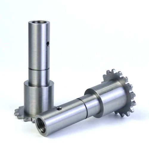

Material:Q235, Q345, 1020, 1045, 17CrNiMo6, 20Mn2 etc
Main Process: CNC turning
Dimensions: Customized
Surface Treatment: Polishing/Sandblasted/Anodized/Chrome Plating/Nickle Plating/Zinc Plating/Silver plating/Carburizing/ Nitriding/ Heat Treatment etc
Standard: GB, EN, API650, China GB Code, JIS Code, TEMA, ASME
Application: Automobile parts, wind power generation equipment accessories, ER fluid, medical apparatus and instruments, machinery parts, lighting components, hardware accessories, electric motor products, medical equipment parts, electronic Industry, transportation Industry etc
Hardware machining parts, stainless steel machining, CNC machining, non-standard parts
Gear Specifications: Determine the gear's parameters such as the number of teeth, pitch diameter, module (in metric systems) or diametral pitch (in imperial systems), pressure angle, and face width. These parameters are crucial as they affect the gear's performance and its meshing with other gears. For example, the number of teeth determines the gear ratio when it is in a transmission system.
Material Selection: In our sheet metal fabrication services, choosing an appropriate grade of steel is important. Commonly used steels for gears include carbon steels (such as 1045 steel) and alloy steels (like 4340 steel). The choice depends on factors such as the required strength, wear resistance, and the application's load - and - speed conditions. Alloy steels are often used for high - load and high - speed applications due to their better mechanical properties.
Stock Cutting: Cut a piece of steel stock to a size slightly larger than the final gear dimensions. This can be done using sawing machines like a bandsaw. The extra material allows for subsequent machining operations such as turning and milling to achieve the precise gear shape.
Heat Treatment (Optional): Depending on the steel grade and the intended use of the gear, a heat - treatment process may be necessary. Forging can be used to shape the raw material and improve its internal grain structure. Annealing can relieve internal stresses in the steel, making it more machinable. Case hardening methods such as carburizing or nitriding can be applied to increase the surface hardness of the gear to improve wear resistance while maintaining a tough interior core.
Turning: Use a lathe to turn the outer diameter and the bore (if applicable) of the gear blank to the approximate dimensions. This operation helps to create a cylindrical shape and accurate diameters for the gear. The gear blank is mounted on the lathe's spindle and rotated while a cutting tool is fed along the workpiece to remove material.
Milling: Milling is a crucial step for creating the gear teeth. A milling machine with a gear - cutting cutter is used. There are different types of milling cutters for gears, such as involute gear cutters. The cutter rotates at high speed and is fed into the gear blank to gradually form the teeth profiles. The milling process requires precise control of the cutter's movement to ensure the correct tooth shape and spacing.
Gear Hobbing: Gear hobbing is another popular method for gear machining service. A hob, which is a helical cutting tool with a series of cutting edges, is used. The hob and the gear blank rotate simultaneously at a specific ratio to cut the teeth. Gear hobbing is efficient and can produce high - precision gears, especially for mass production.
Grinding: Grinding can be used to achieve a very fine surface finish and precise dimensions. It is especially important for gears that require high accuracy and low surface roughness to reduce friction and wear. The grinding wheel is used to remove a small amount of material from the gear surfaces, including the teeth and the bore.
Lapping: Lapping is a finishing process that uses a fine abrasive slurry between the gear and a lapping tool. It helps to further improve the surface finish and the accuracy of the gear teeth. This process can correct minor shape errors and produce a very smooth surface for better meshing performance.
Dimensional Inspection: Use precision measuring tools such as calipers, micrometers, and coordinate - measuring machines (CMMs) to check the gear's dimensions. The pitch diameter, tooth thickness, and other critical dimensions must meet the design specifications. Any deviation from the specified dimensions can lead to problems such as improper meshing and reduced gear life.
Profile and Tooth Contact Inspection: Specialized gear - measuring instruments are used to check the tooth profile and the contact pattern between the gear and its mating gear. The tooth profile should match the involute curve (or other designed profiles) precisely, and the contact pattern should be evenly distributed along the tooth width to ensure smooth power transmission.
Hardness Testing: Use hardness - testing equipment such as Rockwell or Brinell hardness testers to ensure that the gear has the desired hardness. The hardness value should be within the specified range to provide the required strength and wear resistance.
Cleaning: Before assembly, thoroughly clean the gear to remove any machining debris, coolant residues, or abrasive particles. These contaminants can cause premature wear or damage to the gear and its associated components.
Alignment: When installing the gear into a transmission system or other machinery, ensure proper alignment with other gears and shafts. Misalignment can lead to excessive noise, vibration, and accelerated wear. Use alignment tools and techniques such as dial indicators to achieve accurate shaft and gear alignment.


